 The following describes and experiment in relocating the MAF to AFTER the turbo. The MAF used is the LT1 style 3" MAF with the Translator. This is divided into two page ... Phase 1 and Phase 2.
This is my first relocation of a Buick V-6, MAF. From what I've been able to gather, the relocation should be OK. The electronics package is good to 120dC, and the operating temp of the *wires* is 70dC. In what testing I've done, I've never actually exceeded the 70dC, in MAT temps (even if the temp was over the 70dC, I'd imagine that allowances are made for that).. The housing itself shows no real weak stuctural places for failure, from boost.
 The *reason* for this experiment was that for at any air flow per Throttle opening the incoming air would be presented in the most repeatable manner possible. While this might have signifigant meaning for WOT, my primary motivation is for drivibility, and mileage. When using an open element, such as a K+N, the air can be rather erratic in how it behaves in the tract just prior to the MAF. While minor, at times, numbers seemed to vary more then what would make sense to me.
 I
I
've driven hundreds of miles with it so far, and like it. Like I said, I did this for drivibility, and in my opinion there is alot of difference, and all for the good. Trouble is that it turned cold, and I've had to turn the boost down because of road conditions. It's just all too easily blow the tires off. But, rolling into it and running at 15 PSI has all the grin factor of the past.
Also, response in neutral seems markedly improved (much crisper), and idling smoother. How any reversion plays into the new equation is an unknown at this point. I think (as a hunch) think the turbos free running rpm is less of a factor. Like in a panic brake to 0, the immediate idle and recovery is better, but that is one chip area I have been toying with, so it just might be enhancing another variable
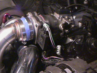
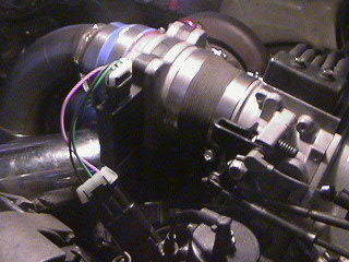
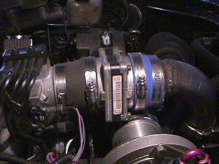
 The MAF to turbo intake pipe clearance is close, even with the 3" MAF, but mine did clear. I'm currently running the Translator +, and extender chip. No adjustments were needed.
The pics show, the current installation with a .5" plenum spacer, which changed the angles some, so it doesn't look as pretty. I'm getting ready for installing the 3.5 when the parts arrive.
Using the tubing graft was an attempt of just cutting my loses in case it didn't work. Two, 2.5 to 3" hoses would look better, and fit easier. I'm currently waiting on some 2.5 to 3.5" hoses, for the larger MAF.
I'm deliberately *risking* going too large, becuase I have a high level of confidence that with this new level of repeatability, might cover for the poorer resolution at the min air flow rates, with the bigger MAF.
Engine notes:
My combination includes:
- 206 MM hydraulic roller cam
- 40#/hr injectors
- Pocket ported heads (smoothed cambers)
- THDP
- ATR 3" single shot
- Enhanced turbo
(the short list)
 Your results will vary. How much I don't know, nor can I forecast. This very well maybe illegal for emissions. You need to check your local laws for what is legal. I strongly suggest that you mock things together and try it before making any perminant changes. Not to be attempted without adult supervision.
 Have fun!