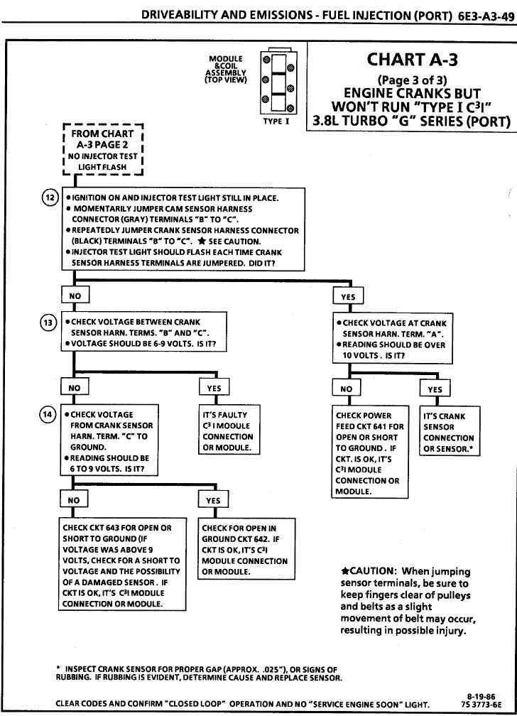
CHART A-3
(Page 3 of 3)
ENGINE CRANKS BUT WON’T RUN “TYPE I C3I”
3.8LTURBO “G” SERIES (PORT)
Circuit Description:
For timing of spark plug firing, a cam sensor 'hall effect" switch is used. The cam sensor sends a signal (Sync-Pulse) to the ignition module when cylinder #1 is 25º after top dead center on the compression stroke. This signal is used to start the correct coil firing sequence and to enable sequential fuel injection. The engine will continue to run if the cam signal is lost while running, however, will not restart after shut down and a Code 41 will be stored.
The crank sensor sends a signal to the ignition module and then to the ECM for reference rpm and crankshaft position. There are three windows in a disc (interrupter) which is mounted to the harmonic balancer. These windows pass by the sensor and as each window passes, the next coil is triggered.
Test Description:
Step numbers refer to step numbers on diagnostic chart.
- Jumpering the Crank Sensor harness terminals "B" and "C" together simulates a Cam signal to the C3I module. Then, by repeatedly jumping the Crank Sensor harness terminals "B" and "C" together, a Crank signal is simulated which should result in the injector test light blinking.
- Verifies a proper Crank signal circuit voltage of 6 to 9 volts and a good ground from the C3I module to terminal "B" of the sensor connector.
- Determines if reason for incorrect voltage reading was due to a fault in CKT 643, an open in CKT 642 of a faulty C3I module.